2.2.5 Communication module (GSM)
Networked objects such as smart devices require a communication module that connects them to the Internet of Things. How can we achieve an economical, technically matching and standardized network solution – “The Right Network”?
In case of short transmission paths, local area networks such as LAN, Wi-Fi or other WLAN solutions (Bluetooth, ZigBee etc.), even near–field technologies can link devices, but for longer ranges only SigFox /LoRaWAN or cellular networks can be used. When data should be routed to cloud databases and later accessed by mobile devices like laptops, tablets and cellphones, existing cellular broadband networking solutions are more convenient. However, this technology soon reaches its limits, the traditional mobile spectrum of a radio cell cannot be overloaded by adding huge numbers of new non-voice subscribers (wearables, connected cars, smart meters etc.)
Serving low data rates of usual smart devices via existing mobile broadband networks such as GPRS, UMTS or LTE would be too expensive, the expected revolution of M2M & IoT requires a solution with the optimal ratio of technical features and cost efficiency.
One of the technological answers of leading providers for low power wide area networking for the M2M communications is the Narrow Band IoT.
It is a relatively new cellular standard of LPWAN radio networking technology based on existing LTE infrastructure. It offers connectivity of a mass of simple devices within a mobile cell, with a low data rate of 600 bits/s – 250 kbit/s as a compromise, developed primarily for transferring small amounts of (sensor) data occasionally, having low energy consumption.
Advantages and key selling points are COVERAGE, BATTERY LIFE, DEVICE COST and DEEP INDOOR PENETRATION
As cellular networks already offer very good area coverage in cities, the advantage of NB-IoT appears on field and indoor, where - due to the weaker signal-, traditional modules consume more energy. The deep indoor penetration is achieved by a higher power density, as radio transmissions are concentrated into a narrower carrier bandwidth, and also repetitions are possible in case of poor coverage at the expense of lower data rate. The small packages transferred in long intervals require minimal energy, thus offering the key feature of NB-IoT, the extreme long battery life. The broadband (GSM/3G/4G) modules utilize services like mobile voice, messaging and high-speed data transmission, which are not required when only low speed, but reliable data transfer is the requirement. Leaving out these functions make the modules cheaper and energy efficient.
In summary, there are strong market trends pointing at growing demand for NB-IoT applications, Endrich, together with its cellular module manufacturer Fibocom would like to be pioneers of this technology.
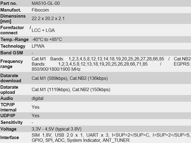
The 4G LTE NB-IoT N510-GL module is a high-performance Internet of Things module tailor-made for the global IoT market and is packaged in LCC+LGA.
It is an ideal Internet of Things module supporting LTE Cat NB1/NB2, especially suitable for IoT industry applications with low power consumption and ultra-small size as core requirement. Relying on the existing 4G network, the NB-IoT module is widely used in Internet of Things scenarios. Fibocom MA510 is a series of multi-mode LTE Cat M/Cat NB2/EGPRS module with global bands, global certifications and GNSS integrated. It is fully compliant to 3GPP Rel-14. Also, MA510 is pin-to-pin compatible with Fibocom LTE Cat M module 510 family, allowing customer applications to immigrate easily between different technologies without hardware changing.
With small size and ultra-low power consumption, rich set of internet protocols, industry-standard interfaces and features, MA510 is suitable for IoT industry applications such as smart metering, smart parking, smart home, wearable devices, wireless POS, trackers,etc.
Fibocom’s low-speed and low power consumption product portfolio offers the ultra-flexibility to industry customers, including N510 (NB-IoT), G510 (GSM), and MA510 (GSM/NB-IoT/eMTC three-mode), the three pins are compatible, which is convenient for customers to switch seamlessly in their IoT projects.
Up to now, Fibocom's MA510 LTE Cat M module has passed FCC/ PTCRB/ CE-RED/ GCF/ IC/ RCM/ JATE/ TELEC/ Anatel/ NCC; and telecom operators’ certifications such as AT&T, Verizon, Sprint, KDDI, Vodafone.
These are the major reasons that we selected this perfect modem to be responsible for the Endrich IoT communication tasks.
Features:
- AT Command Set: 3GPP TS 27.007 and 27.005, proprietary FIBOCOM AT commands
- TX Power: GSM850/900: 32.5dBm 2dB DCS1800/PCS1900: 29.5dBm 2dB Cat M1: 23dBm 2dB (Power Class 3) Cat NB2: 23dBm 2dB
- Data transmission speed:
- Cat M1: Max 375Kbps (DL)/ Max 1119Kbps (UL)
- Cat NB1: Max 32Kbps (DL)/ Max 70Kbps
- Cat NB2: Max 136Kbps (DL)/ Max 150Kbps (UL)
- EGPRS: Max 296 K bps (DL)/ Max 236.8 K bps (UL)
- GPRS: Max 107 K bps (DL)/ Max 85.6 K bps (UL)
- Features supported :
- PPP/TCP/UDP/SSL/TLS/FTP(S)/ HTTP(S)
- MQTT/CoAP/LWM2M
- VoLTE/NITZ/PING/Jamming Detection
- DFOTA
2.2.5.1 Power supply
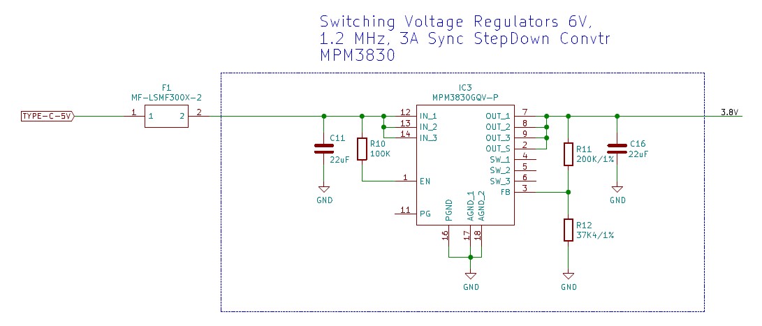
The power supply of the GSM modem should provide 3.8V. In case of the input is USB power (5V) we have used Monolithic Power System’s minimodule MPM3830 with high current handling capabilities as the maximum required current is 3A (at requesting connection to tower in GPRS mode).
The MPM3830 is a step-down module converter with built-in power MOSFETs and inductor. The DC-DC module comes in a small surface-mount QFN-20(3mm x 5mm x 1.6mm) package and achieves 3A continuous output current from a 2.7V to 6V input voltage with excellent load and line regulation. The MPM3830 is ideal for powering portable equipment that runs from a single cell LithiumIon (Li+) Battery. The output voltage is regulated as low as 0.6V. We only needed 3.8V with this high constant current, so we used it when the board is powered from USB. Only FB resistors and input and output capacitors were needed to complete the design.The Constant-on-time control (COT) scheme provides fast transient response, high light-load efficiency and easy loop stabilization. Fault condition protection includes cycle-by-cycle current limit and thermal shutdown (TSD).The MPM3830 requires a minimum number of readily available standard external components and is available in an ultra-small QFN20 (3mmx5mm) package. Its datasheet can be downloaded from the below web link, or by using the QR Code on the right side.
The schematics is as follows:
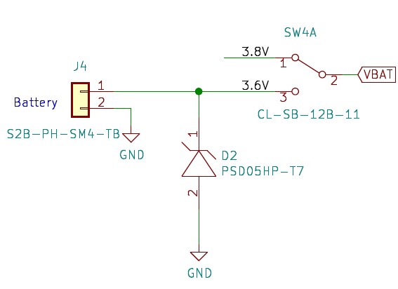
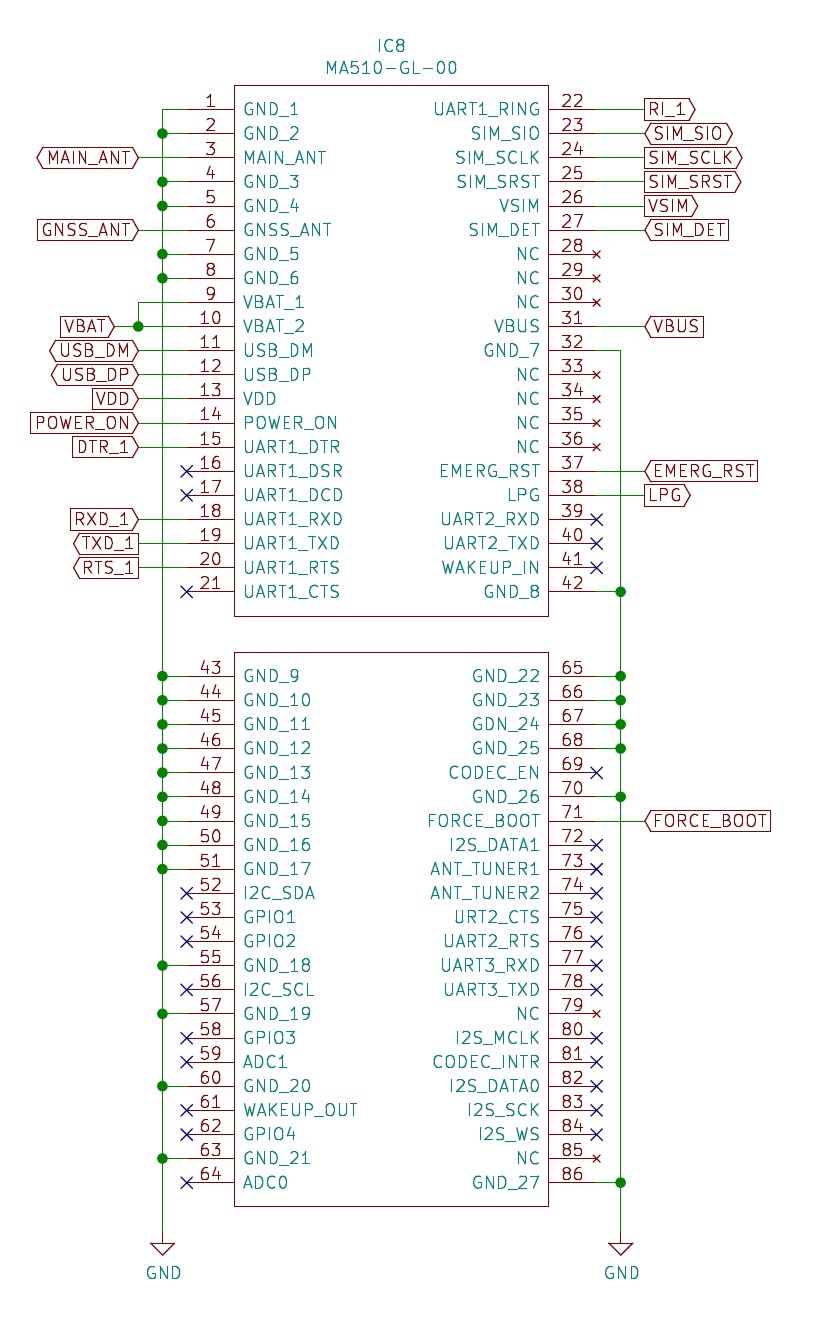
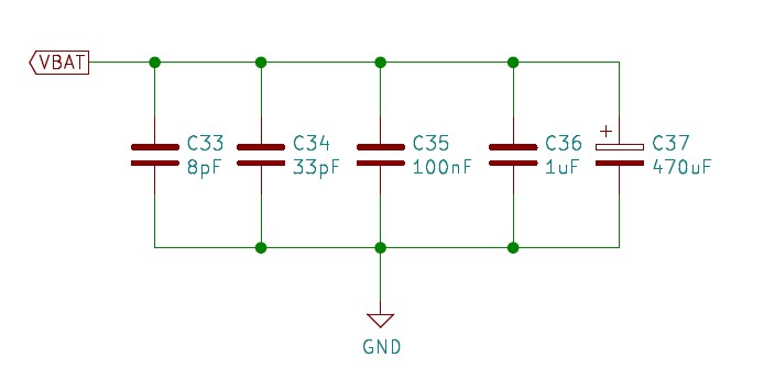
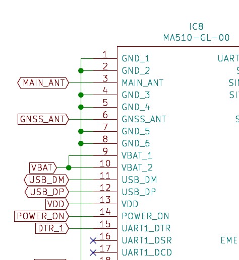
In case the power is supplied by a lithium primary pack, the mode switch (SW4A) should be in 2-3 (3.6V) position. As the modem is able to work on the voltage range of 3.3V- 4.5V (typical 3.8V) , the 3.6V provided by the battery pack is fine without any boost conversion. The VBAT line (3.6V in this case) is connected to the VBAT_1 and VBAT_2 (PIN 9,10) of the MA510-GL-00 GSM modem. The stable power supply ensures the proper functioning of the module.The design allow not more than 150 mV ripple voltage on the power line. The power supply has to be extended with different filter capacitors with total circuit ESR<50 mOhms to reach adequate filtering according to the next figure. The 470 uF voltage stabilizing capacitor is a low ESR electrolytic type of capacitor, its main function is eliminating power supply fluctuations. The 1uF and the 100nF capacitors are for digital signal noise filtering purposes, they are responsible for filtering out interferences from the clock and digital signals. The 8pf and the 33pF capacitors are for filtering RF noise at low and intermediate bands ( 900 MHz and 1800 MHz).
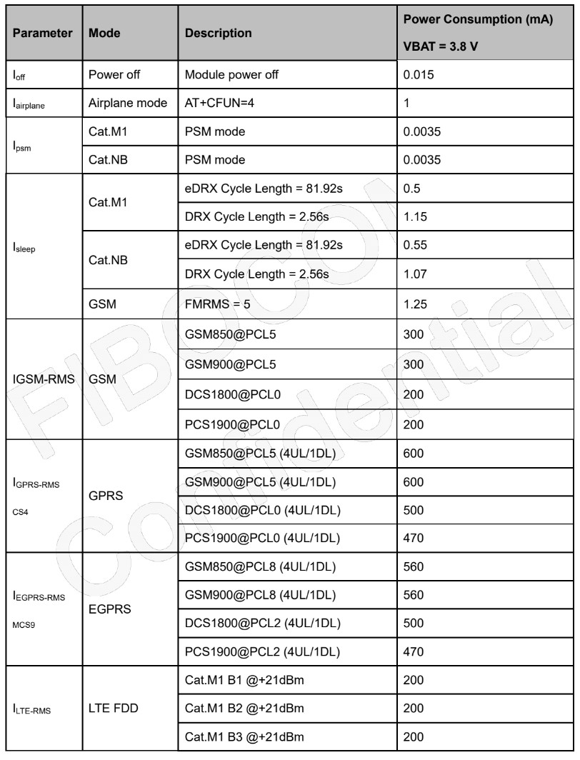
The power consumption of the module in different operation modes can be seen in the below table. The maximum power consumption can be experienced in 2G mode (GPRS & EGPRS) , while the power saving mode of the LTE_M and NB-IOT mode are the smallest power consumption states of the modem (0.0035 mA). The current consumption in sleep mode at all three operation modes (2G/LET_M & NB-IoT) are around 0.5-1.25 mA.
The effective current in LTE-M and NB-IoT mode @ +21dBm are around 200 mA.
2.2.5.2 Controls and signals
Visual feedback:
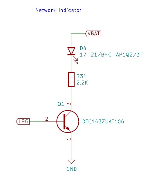
The network indicator LED is driver by a transistor connected to the LPG output of the modem and pulled up to the Vcc of the modem (3.6-3.8V). The D4 blue chip LED is called the NETLIGHT LED offering visual feedback about the operation of the modem.
Control switches :
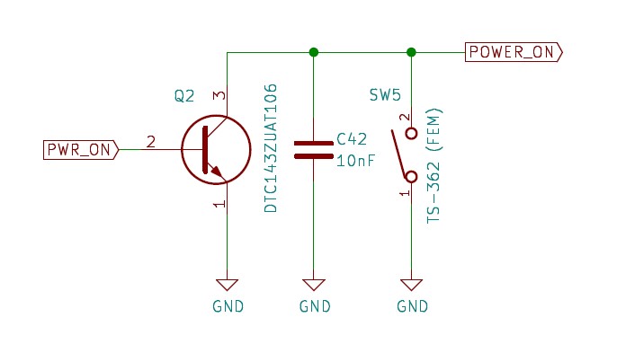
The power ON/OFF signal may come from the MCU unit’s PA8 GPIO or can also be generated by a push switch ( SW5). The hardware power ON function can be activated by pulling the POWER_ON input of the modem down to GND for at least 0.55sec ( upto 1.7 sec) and for power OFF at least 3.5 sec ( up to 7 sec).
Ther is also a possibility to power off the modem with a software switching from inside the modem by applying AT command AT+CPWROFF.
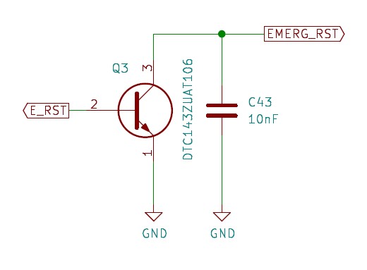
The RESET signal of the Modem may come from the E-RST pin (PB8 GPIO) of the MCU. The EMERG_RST input of the modem should be pulled to GND for about 7.5..8.5 sec. There is also a possibility for a software reset from inside the modem itself by using the AT+RESET command.
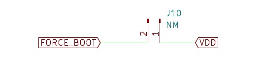
Force Boot of the modem is possible by connecting FORCE-BOOT pin of th emodem to VDD when powering up the modem in order to enter to forcible upgrade mode. This can be done by shorting the jumber J10 prior to power on.
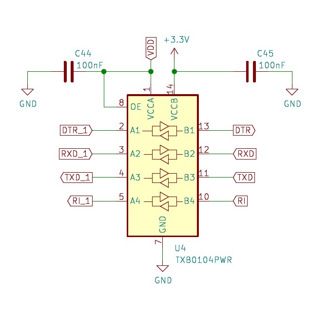
2.2.5.3 Level adjustment
As the modem Vcc (3.6..3.8V) is higher than the MCU Vcc (3.3V), the matching digital lines (serial data lines) should also have a level adjustment in between. This is done by the Texas Instrument’s TXB0104PWR level translator IC on our board. The left domain is powered from the GSM modem’s VDD (3.8V) and the right domain, which is connected to the MCU gets 3.3V DC.
2.2.5.4 Interfaces
Serial DATA lines:
The modem is connected to the MCU via its UART (DTR, TXD, RXD, RTS) through a level translator described in 2.2.5.3. The AT commands controlling the MODEM are transferred from the MCO to the modem through these lines and the answers of the modem also arrive on this channel.
USB:
There is a USB connector on the side of the board directly connected to the GSM modem. Through this port one can easy access the modem from an external PC’s terminal emulator ( see 3.2).
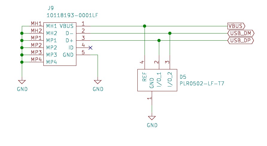
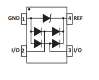
The USB interface of the board is protected against ESD and EFT by using ProTEK Devices’ PLR0502-LF-T7 transient voltage suppressor diode array. The PLR0502 is an ultra low capacitance (0.6pF) steering diode and TVS array combo. This device provides circuit protection for interfaces and wireless bus applications and portable electronics. The PLR0502 is ideally suited to protect USB(1.0-3.0) data I/O ports against the effects of ESD and EFT. The PLR0502 meets the requirements of IEC 61000-4-2 (ESD) and IEC 61000-4-4 (EFT). At higher operating frequencies or faster edge rates, insertion loss and signal integrity are a major concern. The PLR0502 offers a ultra low capacitance and low leakage current in a SOT-543 package.
The datasheet of the device can be accessed in the below link or by scanning the QR code on the right:
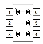
SIM Card interface:
The SIM card socket of the board is directly connected to the GSM modem as visible on the figure. The ESD protection is provided by ON-SEMI SMF15CT1G 5-Line Transient Voltage Suppressor Array. This TVSD array is designed for application requiring transient voltage protection capability. It is intended for use in over−transient voltage and ESD sensitive equipment such as computers, printers, automotive electronics, networking communication and other applications. This device features a monolithic common anode design which protects five independent lines in a single SC−88 package.
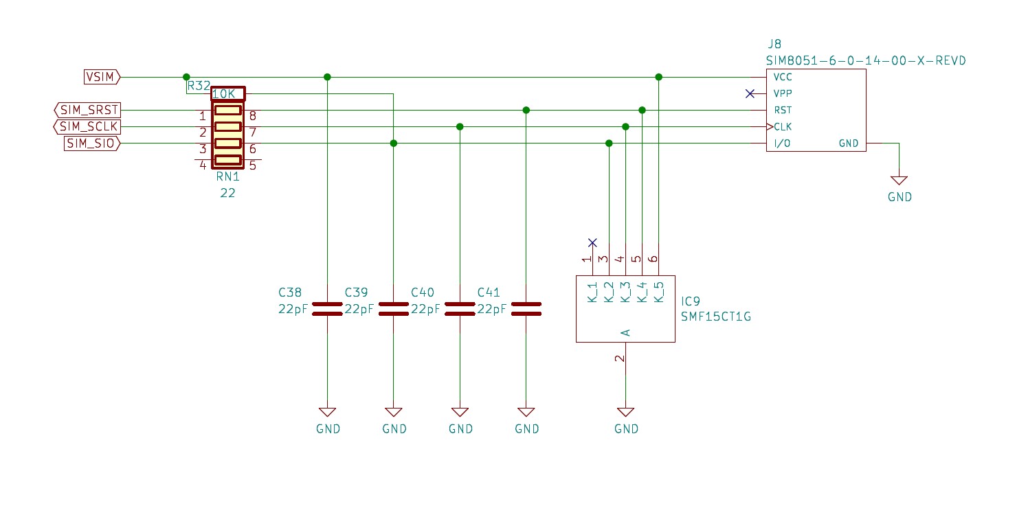
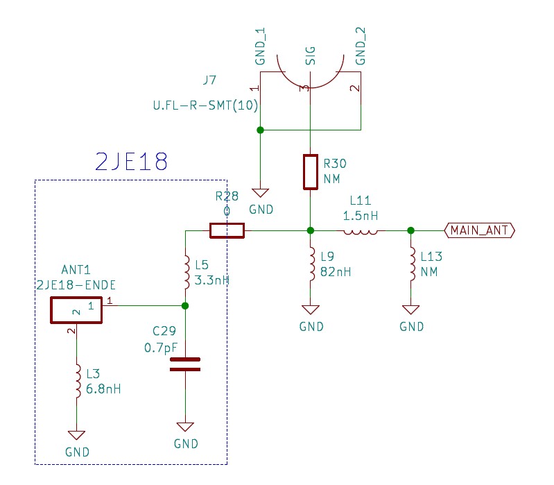
Antenna Interface:
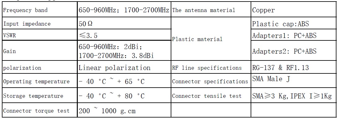
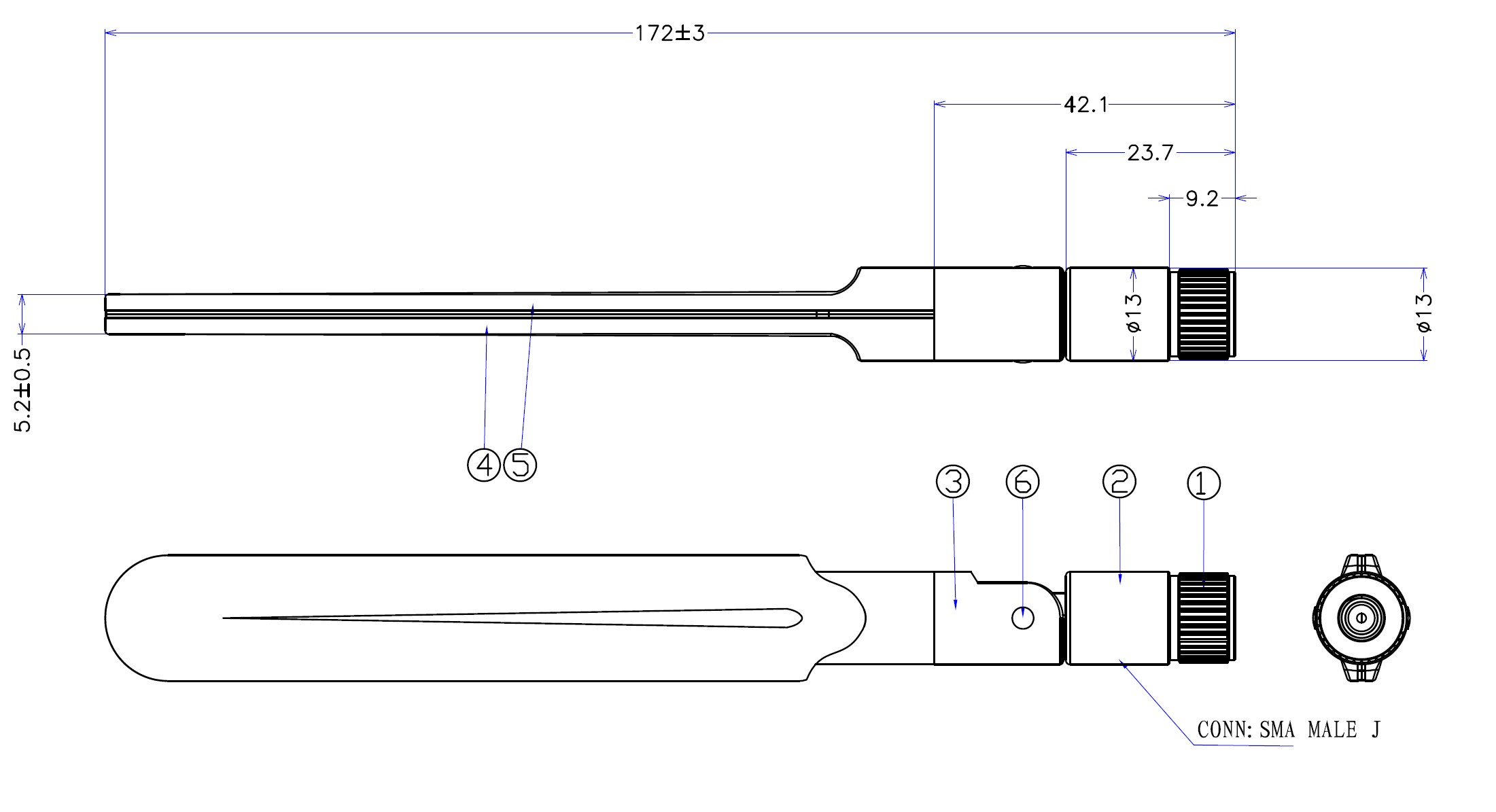
The IoT SBC board has on board GSM and GNSS antennas for the GSM modem, as well as antenna connectors for external aierials. The schematics are as seen on the figure. 2JE18 is a 4G LTE/3G/2G High Performance Compact Size Fiberglass Antenna from 2J, that may be used when the board has good access to GSM signal. Its datasheet can be accessed :
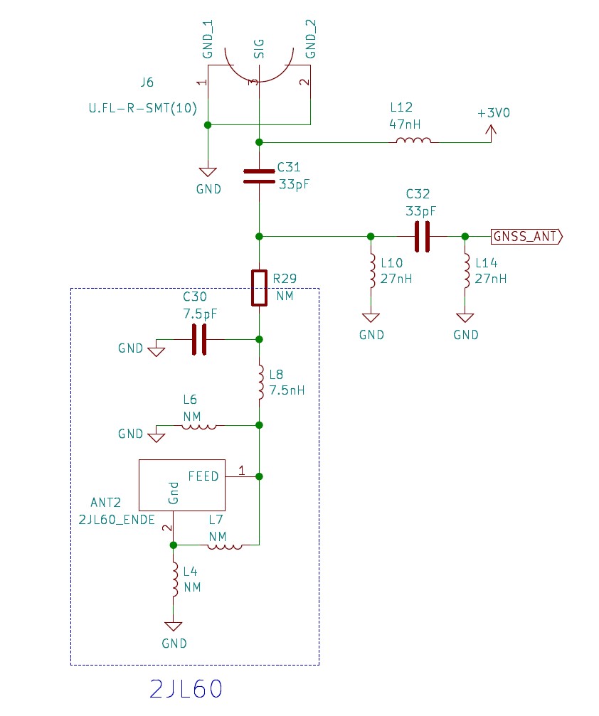
2JL60 is a GPS/GLONASS/BeiDou/QZSS/Galileo Ceramic Antenna from 2J, this is responsible for a god GNSS signal when direct visibility of satellites is possible. Its datasheen can be found here :
External antennas:
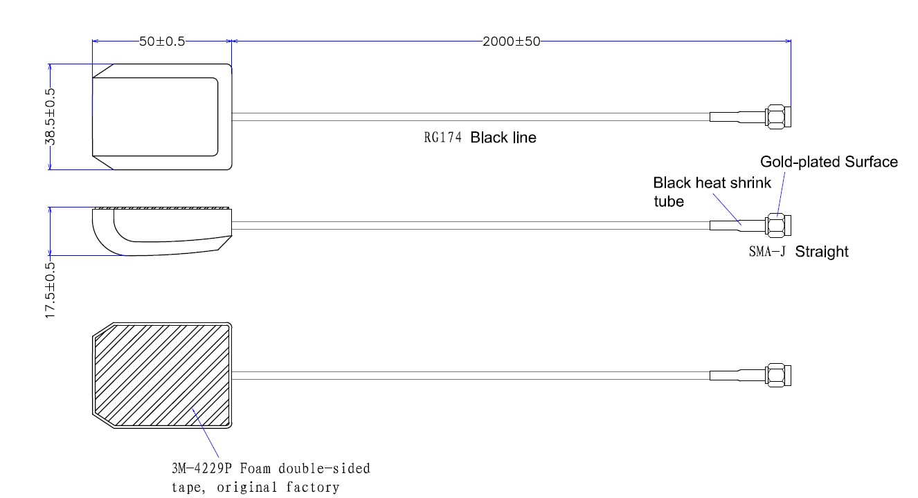
For being able to use the Endrich IoT SBC board indoor with worst penetration of signals, external airil connectors have been placed to the board for GSM as well as GNSS signals. We are suggesting to use the antennas Fibocom used for RF approval processes for their model MA510 from manufacturer BGS (Shenzhen Bogesi Communication Technology Co.,Ltd). The LTE antenna is BGS-015D.
Datasheet is available :
The GNSS antenna is BGS-607C. GPS & Beidou Passive Antenna was composed of ceramic antenna body, reflector and feeder cable.
Datasheet is available :
2.2.6 Battery (operation from Li power source)
The Endrich IoT SBC Board may be operated also by battery power source. In case this is an USB power-bank, there is no difference compared to the conventional USB power option. However if the source is a primary Lithium battery, it is good to know the technical background.
To find energizing solution for an IoT node is a challenge, it is definitively a serious consideration to select the right primary battery. The disposable batteries available on the market today are manufactured in various form factors, and usually their chemical systems are completely different. The old carbon-zinc batteries have been replaced by well know alkaline batteries, and today the focus of engineers turn to the lithium batteries, that are lightweight, more durable and chargeable than everyday batteries.
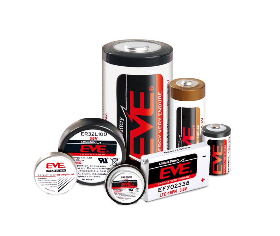
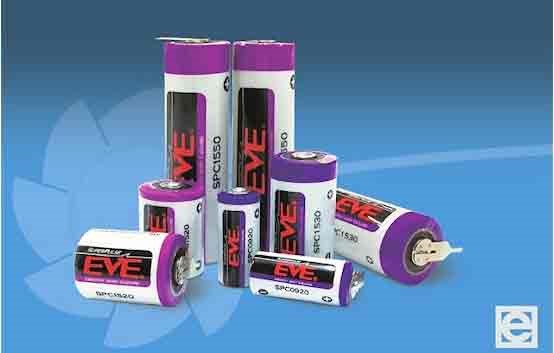
To support selection of lithium disposable batteries, we try to overview the technical possibilities, the technical features and suggested applications of the different types through the product range of the World leading lithium metal primary battery manufacturer EVE Energy.
Lithium technology– disposable batteries
Battery is an energy storage system, that converts chemical energy to electronic energy due to its capability to generate electric charge by chemical reaction, The chemical reaction creates free electrons, that can flow as electric current, that we can use to energize circuit placed between anode and cathode.
If the chemical reaction is not reversible after the discharge of the battery, one of the materials of the reaction runs out, we talk about primary or disposable device, that should be replaced. If the charge can be recovered by using external electric current, we talk about rechargeable or secondary battery.
During the technology development the feasibility to use lithium as the lightest, lowest density metal, with highest electrochemical potential and best energy storage/weight ratio came into view. Technical literature uses ‘lithium or lithium metal batteries’ phrase for the disposable types with lithium anode. These are not to be mixed up with the lithium-ion rechargeable accumulators, that have no lithium anode, but graphite, and their cathode is a composite of lithium and some transition metal-oxide like nickel, cobalt, manganese or iron oxide. Usually the electrolyte is a lithium salt dissolved in a kind of organic carbon solvent.
When discharging, the rapid reagent lithium gives up one of its electrons, and transforms into Li+ ion, the free electron flow results the electric current. When recharging, the Li+ ions flow back and intercalate into the anode’s porous graphite material, forced by the external voltage caused electromotive force, and the system will be ready again to generate electrical energy. Next to the conventional Lithium-Ion accumulators, at the end of the nineties new type of rechargeable batteries came into focus, the so called lithium-poly families, that use solid polymer composite electrolyte instead of liquid, and instead of the hard metal case of Li-Ion types, these devices have flexible cover shell, and manufactured in diverse tiny sizes. Although their capacity is usually smaller, they can be better used in portable electronics.
General properties of lithium-metal primary batteries
Temperature/Humidity
The biggest enemy of batteries is heat, the self-discharge of primary batteries stored on high temperatures may grow as high as 35%. Ideal storage conditions are characterized by humidity between 40-90% and temperature range of +10°C to +25°.
Nominal capacity
The nominal capacity is the multiplication of discharge current (A) and the time to discharge (h) by definition.
C= I (A) * t (h)
Capacity is the charge value that is available during discharging from fully charged status to the moment the breakdown voltage is reached on given discharge condition (discharge current & C-rate). Serializing batteries, the capacity will now grow as their currents stay the same, however due to the multiplication of the voltage, of course power will grow (P=U*I).
Battery voltage
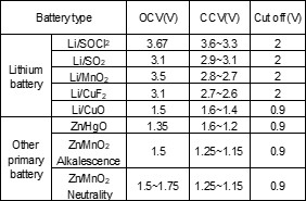
To describe voltage of battery on a satisfactory way, we need to define several different voltages, that all characterize battery behavior.
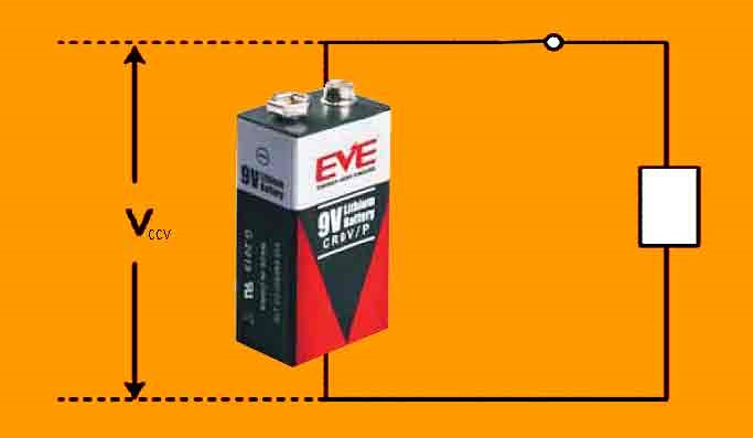
Nominal voltage is the primary reference voltage, however in practice we have to distinguish between voltage without load, the open circuit voltage (OCV) and during discharging the close circuit voltage (CCV).
The voltage value, where the battery is considered fully discharged, is called the breakdown or cut-off voltage.
Passivation
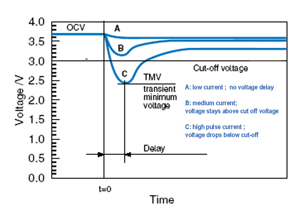
Passivation is a phenomenon of lithium primary cells related to the interaction of the lithium metal anode and the electrolyte. A thin so called passivation layer forms on the surface of the anode at the moment the electrolyte is injected into the cell during production. This layer is important because it protects the anode from reaction while the cell is not affected by load, resulting in a long shelf-life. Under load, when battery starts to discharge, the current flowing through the cell will start to rebuild this layer. Under normal conditions, the thin passivation layer does not affect or degrade the performance of the battery cell. When the layer grows too thick due to long storage, discharge performance may be affected. The development of the passivation layer is influenced by the conditions of the storage, long unloaded periods of months or years and keeping the cells above room temperature (23-25 OC) will cause the passivation layer to grow thicker. A passivated cell may show voltage delay when suddenly applied under load, the voltage response is delayed. As the passivation layer thickens, the voltage delay becomes more severe. On continued discharge though, the voltage of a passivated cell returns to the level of an un-passivated cell. At low discharge currents the wake-up time of the cell is acceptable, since the voltage response arrives in time, however if cell has to serve high pulse current, the voltage may decrease under cut-off voltage.
Providing adequate storage conditions to reduce the chance of passivation is the best way to eliminate voltage delay problems. There are several effective other methods for dealing with excessive passivation when storage conditions cannot be controlled. The layer can be kept from growing too thick by maintaining a light load on the cell during storage. Alternatively, a high load, placed on the cell at regular intervals during storage can be a solution. Applying intelligent programmed start using load just before the anticipated start-up of the cell can also be used to burst the passivation layer and restore normal performance. All of these methods will have an impact on the capacity of the cell. In particular, a low rate discharge tends to increase the normal self-discharge reaction of the cell and reduce the available capacity.
In spite of the problem of the voltage delay, it would be a mistake to consider passivation as a harmful property, as this is the phenomenon that provides lithium primary batteries with extreme long shelf life time. We will detail later a special type of lithium metal batteries, the LiMnO2 CR batteries, that do not suffer from passivation even in case of long storage of years or exposure of excess heat. Other lithium primary systems have to be ideally kept under low and continuous load.
Internal structure
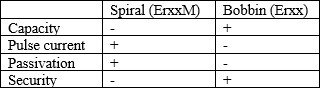
Internal structure of primary lithium batteries is also to be seriously considered, as their effect on battery operation is significant. The cylindrical LiSOCl2 (ER) batteries have either spiral or so-called bobbin structure. Spiral ones are constructed of a high surface metallic foil as an electrode wounded around a core in order to reach high impulse currents, while bobbin type is made as a wire bobbin to store more energy.
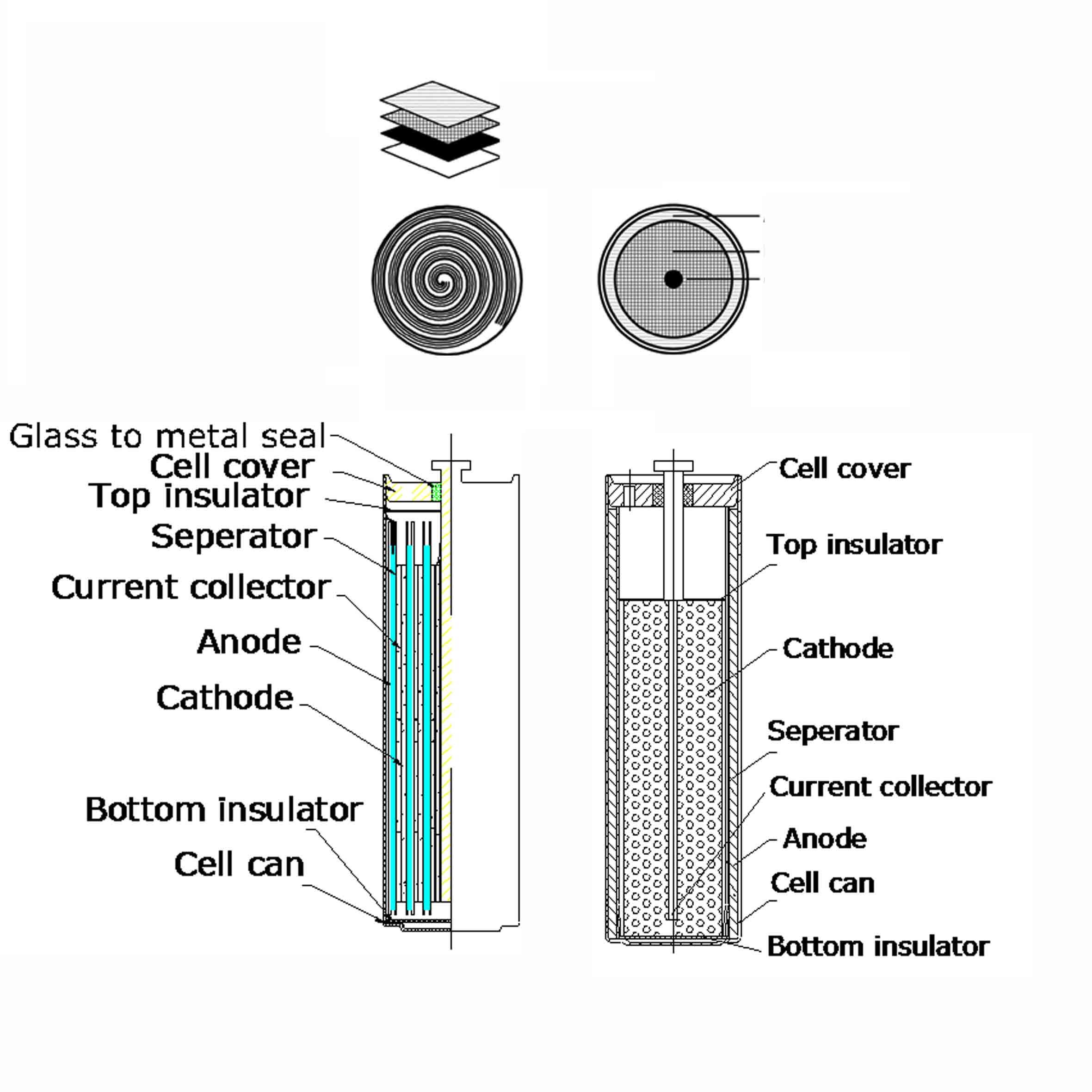
In spiral cells the more space the spiral electrodes take, the less space remains for electrolyte, therefore energy storage capacity is lower, but due to the huge electrode surface their pulse capabilities are advanced. In bobbin cells, the energy storage capacity is 30% higher than spiral versions due to more electrolyte in the can, although the maximum pulse current is low. If design needs high momentary current provided within a short time, spiral cells have more advantages, while in cases high capacity is a must, bobbin types are better to be used. As a matter of fact spiral cells could be dangerous when physical damage occurs due to their high impulse energy delivery capability. Although EVE constructs its spiral ER batteries with well-designed safety vents in order to avoid accidents, it is safer to use bobbin type cell and an additional SPC device in high energy packs. SPC is a device that is connected parallel with ER battery and capable to pump charge with high pulse current to the circuit, while energy is stored in the safer bobbin cell.

Spiral cells have advantage in less voltage delay, as suffer less of passivation than bobbin versions. Above introduced special pack with bobbin cell and additional SPC will however solve this issue, as the SPC is able to pump charge immediately to the system while bobbin type of ER battery is about to wake up in the background.
Part numbering rules
Battery manufacturers follow concerning standards, so it’s quite easy to compare products of different manufacturers. In order to complete the image, we introduce the naming conventions in below table. Primary cells are differentiated by their chemical structure at first, as the first letter of the product code represents.
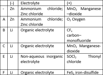
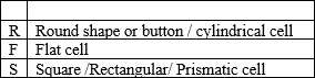
The second letter is for the shape, and the rest represent the size

For IoT applications the below primary families are to be considered, however for the Endrich IoT SBC Board we only recommend to use ER based battery pack (preferably extended with SPC as will be described later).
Li-SoCl2 – Lithium thionyl chloride ERxx/EFxx
Li-MnO2 – Lithium manganese dioxide CRxx/CFxx
Li-FeS2 – lithium iron disulfide AA/AAA
Let us introduce the ER chemistry-based technology in detail:
Li-SoCl2 – Lithium thionyl chloride batteries
As the chemical structure regards, lithium thionyl chloride cells have a metallic lithium carbon - the lightest of all the metals – anode and a liquid cathode comprising a porous current collector filled with thionyl chloride (SoCl2). The chemical reaction that occurs during discharge is as follows :
4Li + 2SOCl2 → SO2 + S + 4LiCl
They deliver a nominal voltage of 3.6V, their open circuit voltage is 3,66V and during load with their 3.4-3,6V closed circuit voltage they are one of market’s highest voltage primer cells. Available in various cylindrical shape, in 1/2AA to D format, with spiral electrodes (e.g. l ER14250M) for power applications and bobbin construction (e.g. ER14250) for prolonged discharge. Lithium thionyl chloride batteries are the primary batteries currently with the highest voltage and energy density (1280 Wh/dm3), longest storage (10-20 years) , and the least self-discharge rate of 1%@20OC. The battery is capable of operation in a wide temperature range normally from -60℃~+85℃. One special has an extended temperature range up to 150℃.Those batteries are ideal for such long-term applications as power for electric devices and electric power, water, heat and gas meters, and especially as backup power source for memory ICS.

UN and UL approvals guarantee safety in delivery and in application.
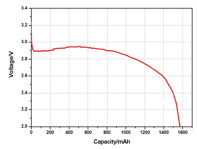
The capacity of the battery determines the time to discharge on a certain discharge current level. During discharge the working voltage of the cell starts decreasing, and at the moment reaching the cut-off voltage, the cell is considered empty.
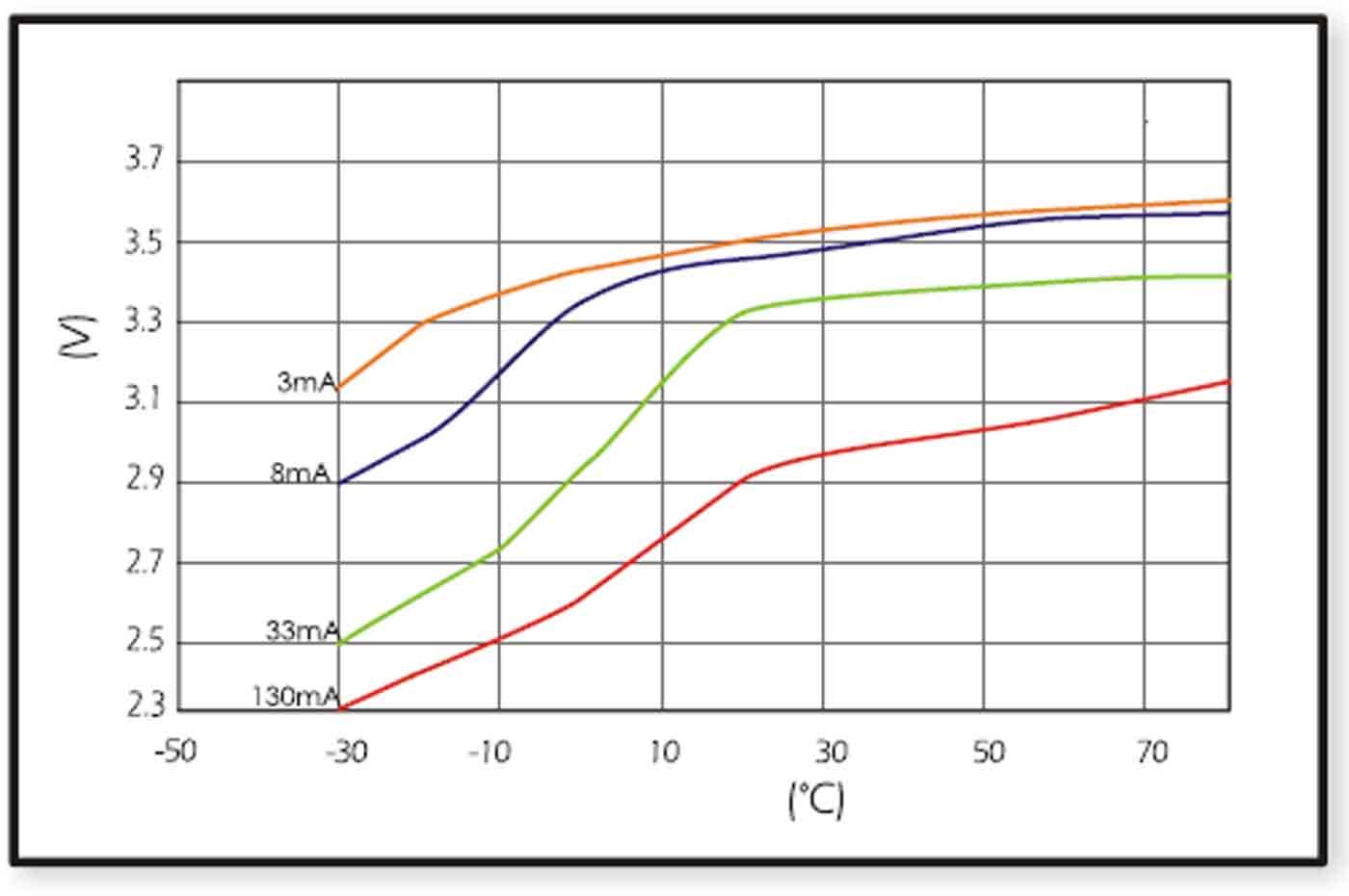
When design-in ER batteries, the effect of ambient temperature to cell behavior should be kept in consideration, as this has a huge influence on discharge characteristics. The figures on the right show the different temperature-voltage characteristics of the two basic structural types of ER batteries (bobbin ER17505 and spiral ER17505M) with different discharge currents.
Spiral cells show less sensitivity to changes of ambient temperature than bobbin type of batteries. They suffer also less from passivation, but their capacity is lower.
For high temperature application such as energizing sensors in mineral or oil drilling heads, we can also offer ER batteries with extreme shock proof and extended temperature range stainless steel encapsulation (ER14250MR-150)
SPC devices & battery packs with ER+SPC
The super pulse capacitors offered by Endrich are momentary high-current discharge devices that can operate in the operational temperature range of -40°C to +85°C. SPC’s unique chemical lithium structure is based on manufacturers’ own patents. The hermetically closed and sealed enclosure with safety valves makes the design superior safe even in applications where traditional super-capacitors cannot be used. One of these area are the gas metering, where SPC with its ATEX approval is an ideal solution for energizing smart-meter’s readout, as the safety valves make the device explosion proof.
The cell voltage is 3.6V, and no passivation appears, which other lithium battery families are suffering from. The self-discharge remains under 2%, which makes it possible to stay long in stand-by more and activate fast to pump momentary large charge into the circuit.
If a smart meter contains a standalone ER (lithium thionyl chloride) battery, the voltage delay caused by the passivation effect may cause problem in operation. Passivation is a phenomenon of lithium primary cells related to the interaction of the lithium metal anode and the electrolyte. A thin so called passivation layer forms on the surface of the anode at the moment the electrolyte is injected into the cell during production. This layer is important because it protects the anode from reaction while the cell is not affected by load, resulting in a long shelf-life. Under load, when battery starts to discharge, the current flowing through the cell will start to rebuilt this layer. Under normal conditions, the thin passivation layer does not affect or degrade the performance of the battery cell. When the layer grows too thick due to long storage, discharge performance may be affected. The development of the passivation layer is influenced by the conditions of the storage, long unloaded periods of months or years and keeping the cells above room temperature (23-25 OC) will cause the passivation layer to grow thicker. A passivated cell may show voltage delay when suddenly applied under load, the voltage response is delayed. In such cases a smart utility meter - being in stand by for a long period of time - will not operate perfectly, the readout electronics may not start, and the data transfer may fail. A possible solution for such cases to use an SPC device in addition to the ER battery.
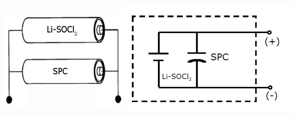
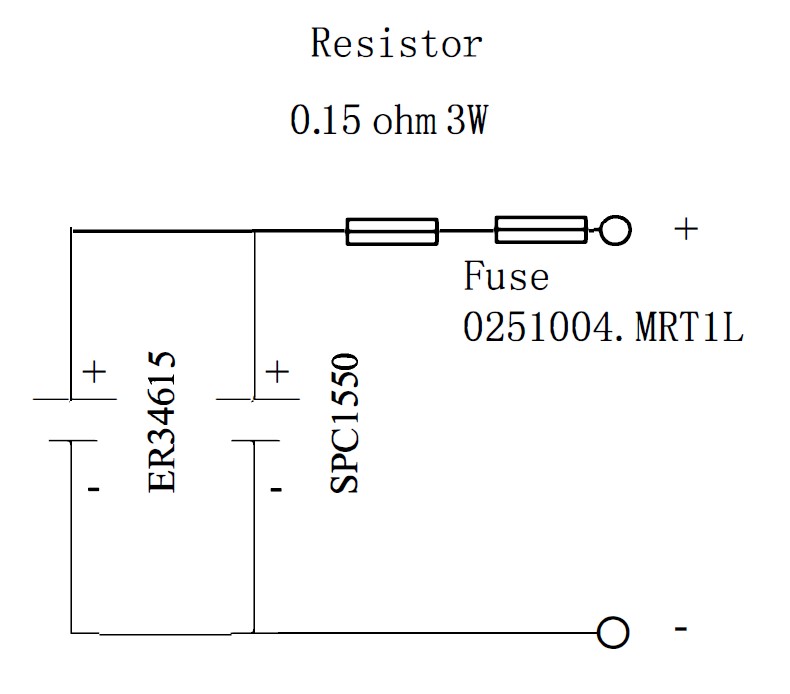
Combined solution: ES energy storage systems
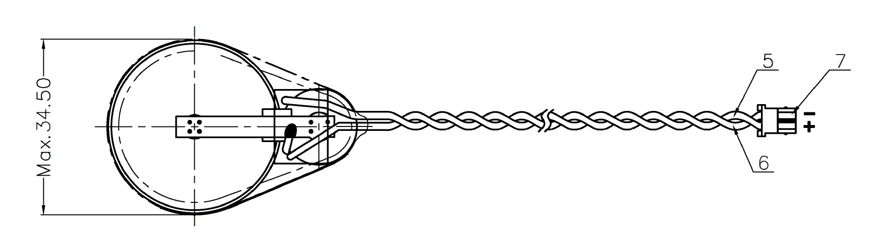
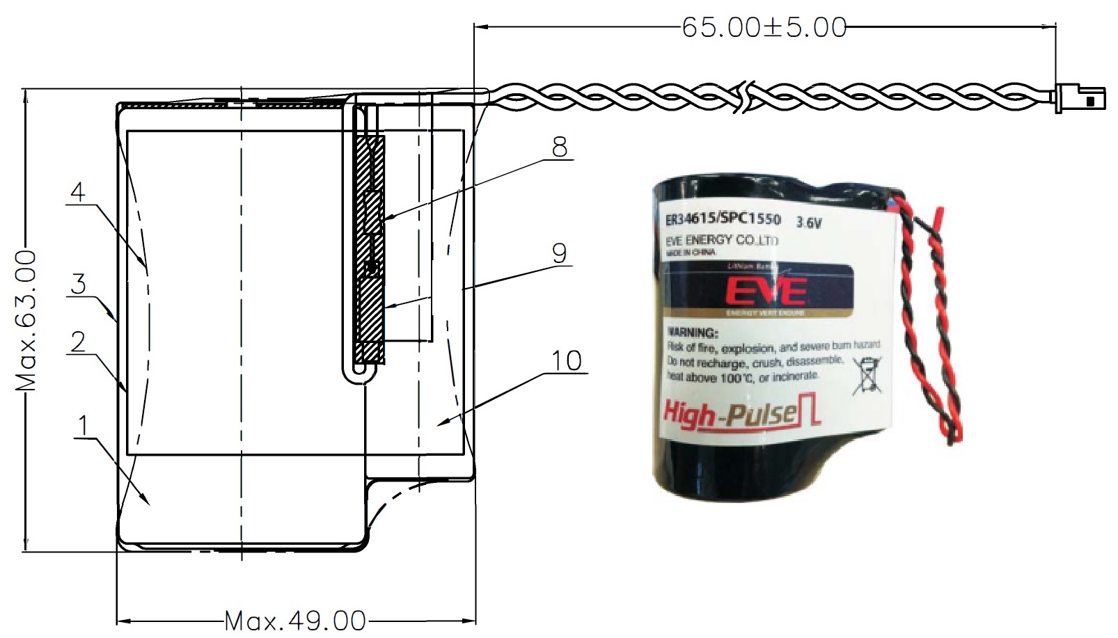
SPC is a standalone device, however on the field it is often used in combination with ER cells, which are responsible for providing enough capacity. By connecting the two cells in parallel, the lithium metal primary battery will keep the SPC fully charged. The ES battery packs are formed by an SPC and a lithium thionyl-chloride (Li-SOCl2) battery as seen on the figure:
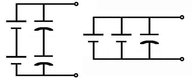
Of course, there are different combinations by means of number of ER cells behind the SPC, or using even more SPC devices in the same time:
Marrying the SPC and the bobbin type ER technologies, we can combine the advantages. Lithium primary battery will store enough capacity and keeps the SPC fully charged all the time, while SPC device is able to pump pulse charge fast to the system. Other manufacturers combine ER batteries with super capacitors, in comparison of the two technologies, the lithium chemistry based SPC systems offer the following advantages:
- Higher cell voltage (3,6V vs max. 2,7V)
- Much smaller impedance (<150 mOhm vs cca. 400 mOhm)
- Higher capacity (>270F vs max 100F)
- Much higher energy density
- By orders of magnitude less leakage current, which is even almost independent from temperature, saving ER battery life (<1uA)
- Much wider operating temperature range
- Much longer service life ( cca 15 years)
- Much safer battery pack (UL1642 UN 38.3)
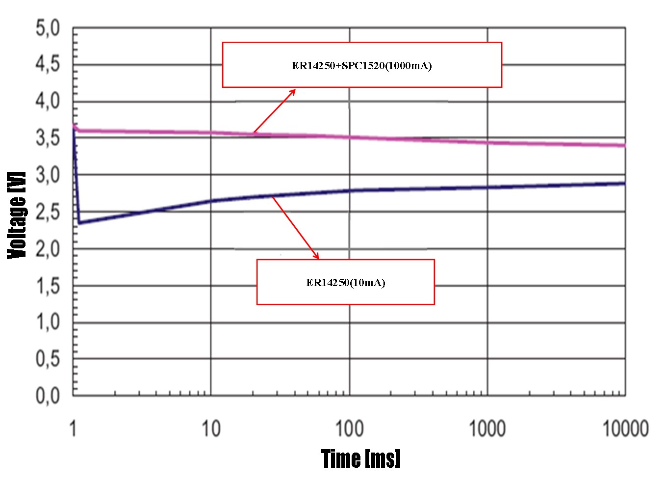
We recommend to use such a combined ER+SPC battery pack to power the Endrich IoT SBC board to provide long service life as well as no issues with passivation (large pulse current, which is required especially by the GSM modem when acquiring a connection to the telecom tower after wake-up)
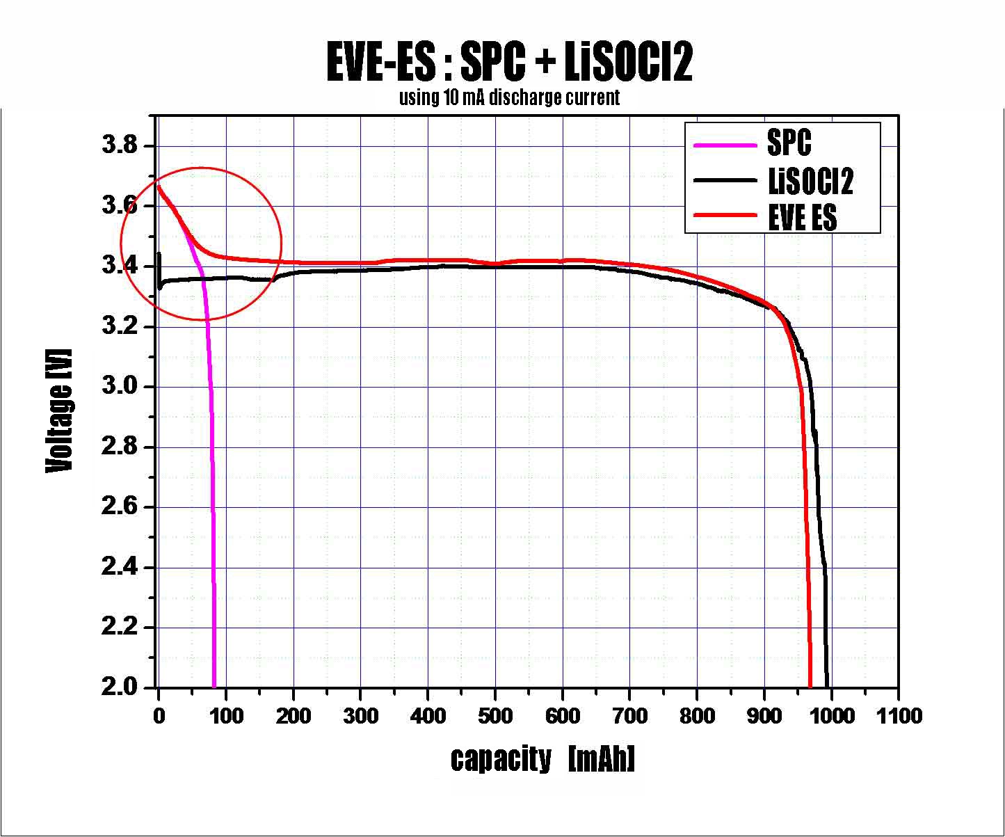
The figure shows, that fast charge pumping of the SPC covers the voltage delay caused by passivation of Li/SOCl2 cell, and the pack voltage never goes below the working voltage of the device. The measurement has been done by using 10 mA continuous load current with a pack formed by an ER14250 battery and an SPC1520 energy storage system.
Other measurements show that the leakage current of the ES system at -30 ℃ stays under 2uA, at +25 ℃ stays under 1uA while at +85 ℃ it will be still below 5uA, therefore considered to be stabile independent from ambient temperature. Lifetime expectation can reach 10-15 years, the pack is able to provide as high as 1A of pulse current, due to its safe construction it can be used in sensitive environment (ATEX). The combined product successfully provides solution for both high energy density (large capacity) and high power-density (high momentary current) requirements.
There are many combinations of ER batteries and different size SPCs, as well more manufacturers available for the IoT industry.
You can find technical data of a few of the combinations in the below data package (or through the QR code).
Datasheet is available :
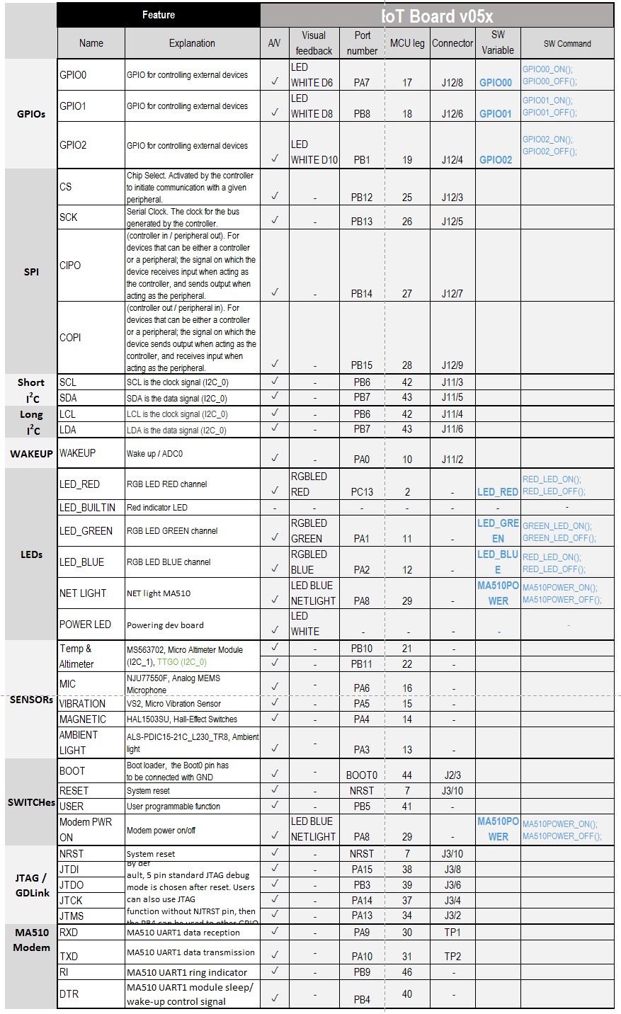
2.2.7 Overview about the controls of the Endrich IoT SBC Board
The Endrich IoT SBC Board has several feedback and control functions that are detailed described in the previous sections. In order to have a short summary, we have created an overview table with the available controls, functions, their connection to the microcontroller unit and the software functions we provide sample codes in the Software Guide.