7 CONNECTING TO THE ENDRICH CLOUD DATABASE
For supporting the everyday development work of our partners’ IoT Engineers, Endrich started a free Cloud Database Service for its contracted partners. A Non-Disclosure Agreement should be signed with the company prior to gain access to the service, please contact your sales partner.
The database can accept connections via UDP ports and store sensors’ data for unlimited number of devices per customer.
7.1 How to get access to the Endrich Cloud Database service
If you intend to use the free service, please contact your sales representative to start the NDA process. At successful agreement you will be provide by a UserName/Password combo, that you can use to access the Administrative Tool, where you can register as many devices as you wish. All these devices may send data to the cloud database via UDP port, and the data can be downloaded later separately for all devices for a certain time period in *.CSV format. Data can be sent for a single sensor or for a set of sensors at once. A special basic WEB based data visualization service is also provided free for all your devices’, where you can see several graphs for the last 100 readings of the sensors.
7.2 Accessing the user interface
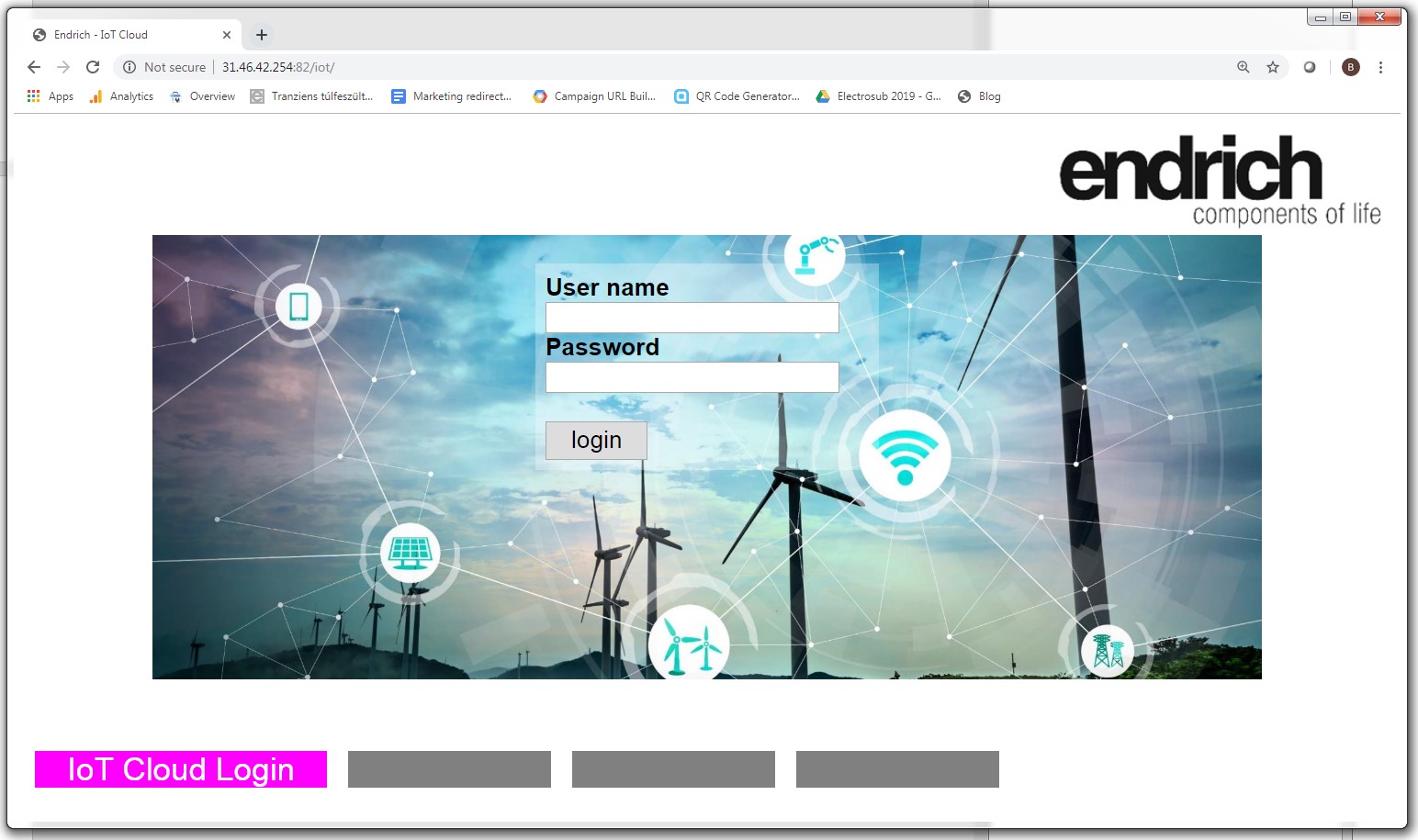
The service is accessible in a web browser (chrome have been tested) using the IP address of the server.
After typing above URL to your web browsers URL line, you get to the LOGIN screen, which offers an entry for the user and device administration area of the Cloud Database Server. Here you can administer your devices ( set up new ones, delete unused ones, collect stored data etc.)
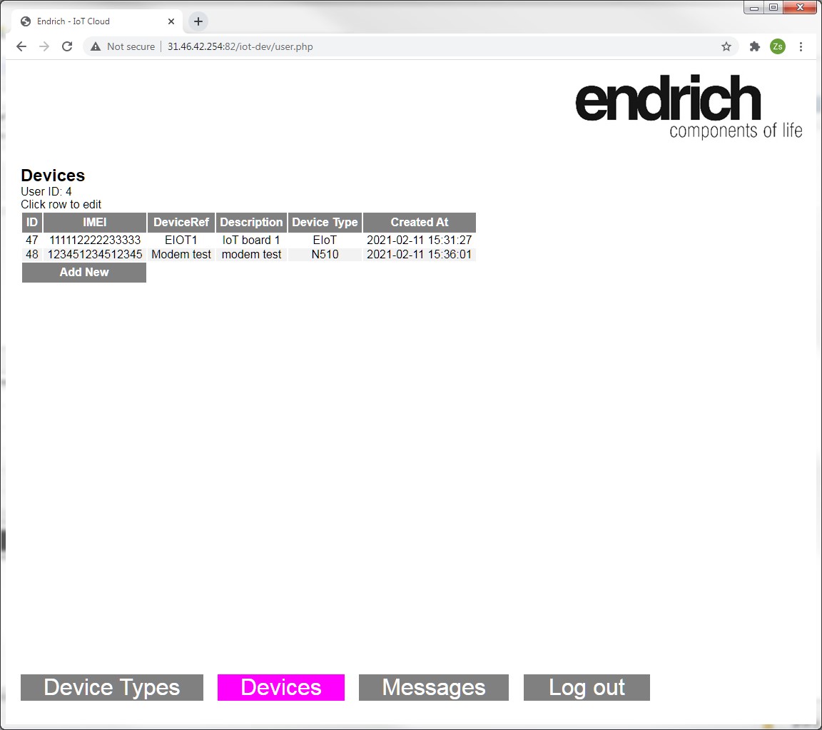
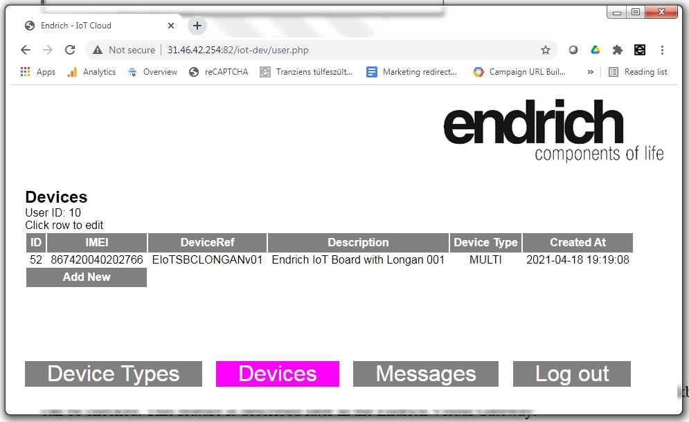
After successful login the user arrives to the administrative area, where – amongst others - it is possible to register new devices.:
7.3 Device registration
When creating a new device, the type of the device can be selected from a drop down listbox from a predefined set of available device-types. Before the first device is added, at least on device type has to be defined, press the Device Type to go to the Device Type definition tool.
Device-types are suggested to mark the communication modem used in an IoT device, such as 2G, 4G, 5G, NB-IoT only or a multichannel module. This is for the user to classify his devices’ communication mode. This is our suggestion only, however one can decide himself how to classify his devices.
To review, add or modify an item please click the Device Types tab. Here you get the list of available Device Types:

Click a row or Add New button to edit a type.
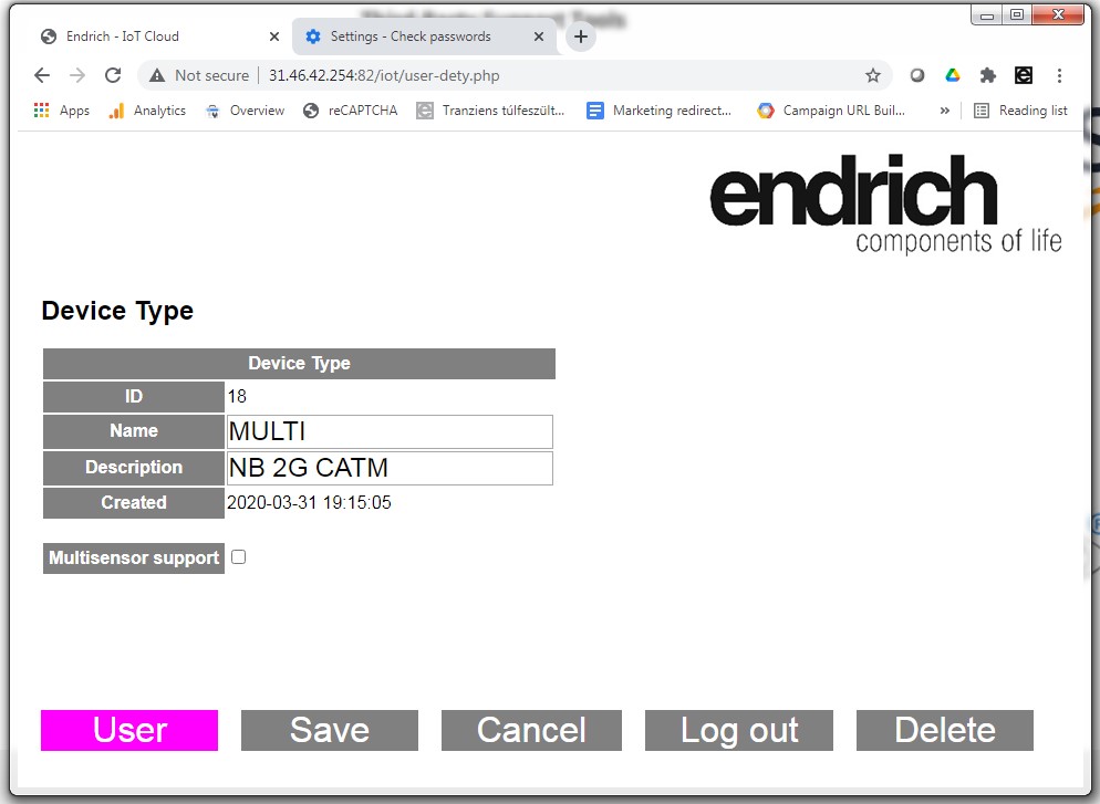
In case this device type will provide readings from multiple sensors, the “Multisensor support checkbox” can be checked. This feature is described later in the Endrich Visual Gateway.
For now please keep the “Multisensor support” checkbox unchecked. The Name and description can be typed on the editing screen. Don’t forget to Save modifications. Once Devices Types List is created ( at least one valid record is added) , you can go to the Device section to create (or modify) devices.
Device can be edited by clicking on a row, adding a new device can be done by pressing the Add_New button.
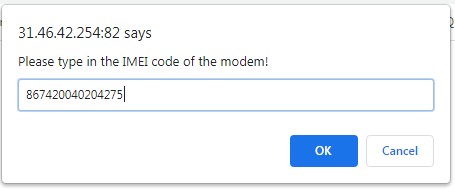
When a new device is defined, we ask for the IMEI number of the modem first in a popup window.The IMEI number must be unique (it is anyway unique as only one modem on the World has this number) since it may be used to identify incoming messages, and can also be used as an identification numberon the Endrich Visual Gateway. We are pre-registering the IMEI numbers of modems on Endrich IoT boards when producing them, so sending messages from the boards and checking the collected data on the gateway becomes possible. If the user registers a new device with pre-registered IMEI number of his own card, it will be registered for him afterwards. In case you don’t intend to identify by IMEI number, you can leave the input box empty, and press OK.
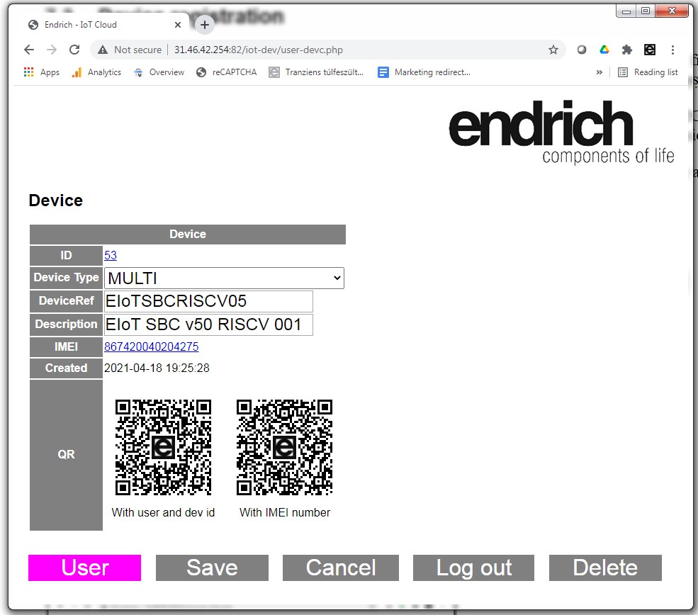
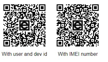
Please select the Device Type from the drop down listbox containing all the Device Types you set up earlier. DeviceRef is a value you can reference and identify the IoT board with, when downloading the data from the ECDB. Description is a free text that you can use for naming your newly added board. IMEI appears as a WEB link, which you can store amongst your favorites in your web browser pointing to the Endrich Visualization Gateway, calling its displaying service for this spectacular card’s sensors graphs. The two QR codes can be used also to access this mini-site with IMEI or Device ID as unique identifiers. It will show the readings of this card’s sensors when multiple sensor support is used in graphical format. When finishing the editing, please press SAVE to save modifications, CANCEL to stop the add process, and DELETE if you would like to drop this device. Please note that the DeviceRef value will be displayed on the message logs. IMEI number cannot be changed, please delete and recrate the device if it would be necessary. (Get in touch with your contact at Endrich for help.) The links of Device ID and IMEI number opens the Visual Gateway with user id / device id or IMEI parameters. The QR codes can be printed and read to access the gateway from smart phones. The Visual gateway works only for device type with Multisensor support (explained later).
7.4 Single- and multi-sensor support
The Endrich Cloud Database policy supports using so called single sensor and multi sensor boards. Single sensor board is meant to be an IoT Device which sends data of one single sensor, such as a Temperature Sensor or a Pressure sensor. Its message only delivers one single data at a time. However the experience shows, there are many IoT Boards (like the Endrich IoT SBC Board), which host multiple different sensors, and it makes sense that all the sensors’ data is transferred in one data package.
In the first case we define an expected datagram ( JSON string) format like this :

User ID and Device ID (in this example, or the IMEI code in the next) identifies the device the message arrives from with a freely chosen message reference value. The “Payload” filed delivers the single sensor’s reading.
When using the MULTI-SENSOR approach, the JSON string is different. Here is the below example JSON, the device is identified by its IMEI code, and the Payload field has a special format:
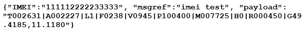
You can see values starting with letters, separated by columns. These are the data arriving in the same time from the various sensors located on the IoT SBC. The letters identify the right sensor on the board.
Of course before sending such multiple data the user needs to set up these sensor fields in the Device Type registration as announced before. Let us go back to Device Type setup and now change the earlier added item’s properties by clicking ON the Multi Sensor Support checkbox :
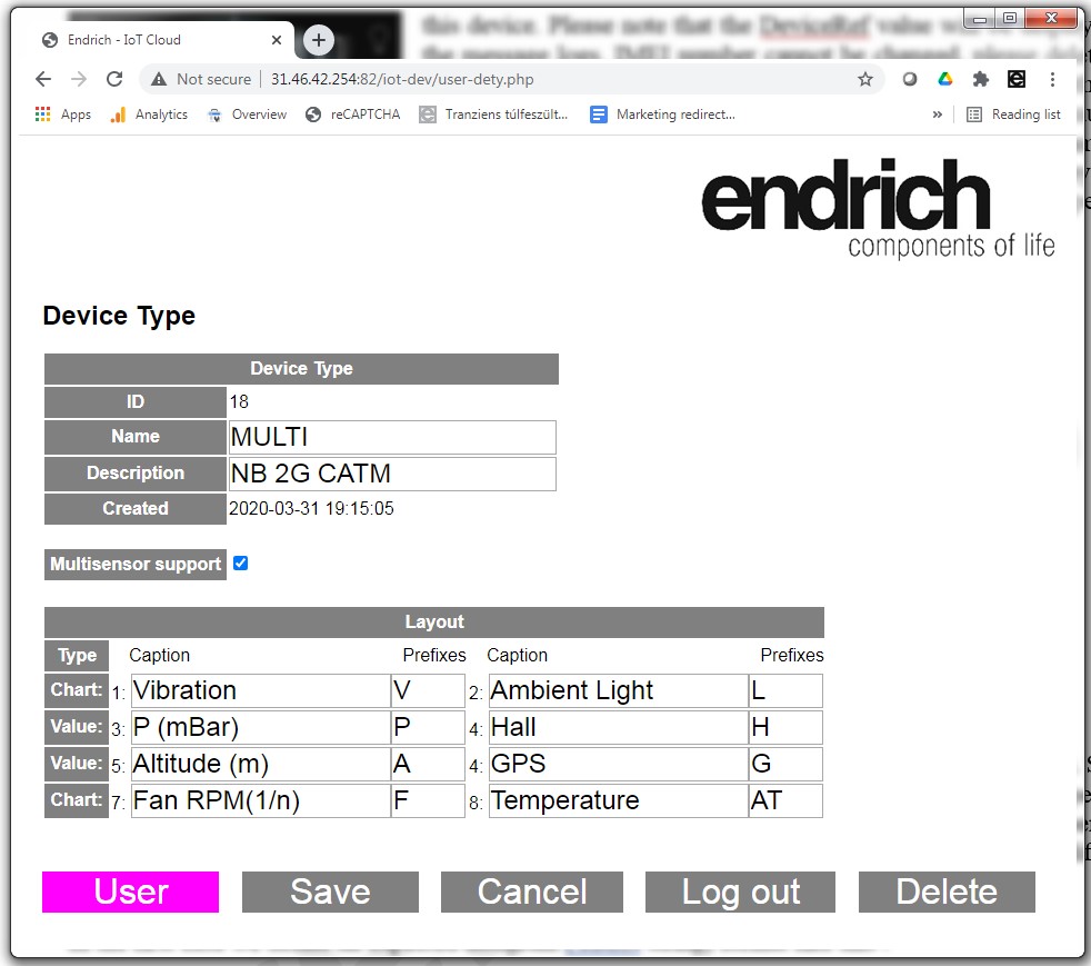
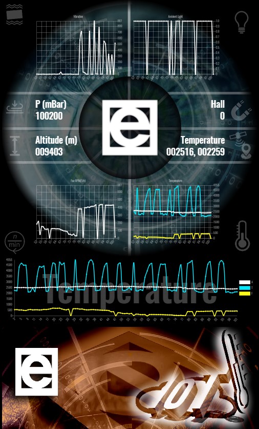
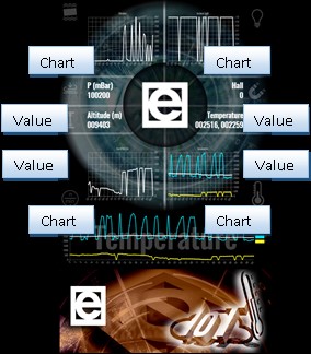
A table comes up with the possibility to define sensors with 4-4 GRAPH CHART or VALUE type of visualization. The screen captions can be set up, as well as the prefixes will be included into the JSON’s Payload field. The detailed explanation will be found at the Endrich Visual Gateway’s system description.
Multi-Sensor support offers the possibility to save energy for the IoT Board, as all data can be sent at once without the necessity to establish GSM connection individually for every sensor. The package size is a bit higher however it still offers big advantages even by using NB-IoT.
7.5 Sending data to the Endrich Cloud DB
The server is listening on UDP port 41234, and logs the received messages if they are in appropriate JSON format.
Endrich uses a single line message format, where the device may be identified in two ways, with user and device ID or by IMEI number:

The userID must be the user ID assigned to the user (when created), and deviceID should belong to the same user (security check done by the server). If such message is received, the device will be looked up from database, and device id, device reference together with the message reference and the payload from the message will be logged. The message reference is supposed to be a custom message reference, while the payload is the real content – the sensor(s) reading(s). The arrival timestamp and the remote IP address and port number are also logged.

In this case the device will be identified by the arrived IMEI code, and the matching User ID and Device ID will be looked up from the database. The IMEI code can be read out from the modem itself by the MCU (ATI command on serial interface), so if this number is assigned to a device in the ECDB, it can be used as unique device identifier and there will be no need to broadcast the used id and device id data in the JSON datagram. If the format was correct, the message is echoed back with a preceding OK+
To send a test message to the Endrich Cloud Database Service any UDP packet sender program can be used. We suggest the following freeware for testing: https://packetsender.com/
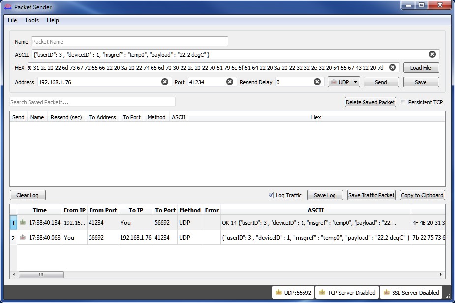
Sending data from your own device you will need to establish a serial link to the modem or board and use a terminal to communicate to it. As the Endrich IoT SBC Board has an USB interface to directly access the modem (see the Fibocom Modem Evaluation Board Mode description in 3.2 and 3.3). it is obvious to try the communication by hand before writing any software for the GD32VF103 MCU. Connect the board to the USB port of your computer follow the instructions of 3.2 and 3.3 and use a terminal emulator to control the modem with the following AT commands:
Supposing UDP port number is 41234 and Server IP address is 78.92.116.254, the commands with NB-IoT communication (ML510 modem of Fibocom) connection commands are as below:
Prior to any attempts to join to the network, be sure that the modem is ON, the blue NetLight LED is active, the SIM card is registering itself. Using empty AT commands time may be given to do the registrations and the serial connection to the modem can be checked. We suggest also to use ATI, in order to get information from the modem, such as its IME and Serial Number.
The AT+MIPCALL command is establishing a connection to the provider’s network, so the APN of the used SIM card has to be used as the second parameter. When successful registration on the network, you get the public IP address of your modem as a result.
The AT+MIPOPEN command will establish a UDP channel between your modem and our Endrich Cloud Database Server on the 41234 port. Please be sure you are using the right SERVER IP address.
The AT+MIPSEND command will send the message to the output buffer, which can be flushed by AT+MIPPUSH. AT+MIPCALL=0 will close the connection to save battery life. The MIPSEND command is structured as below:

To be more simple, we have not coded the content into its binary representation, but in real case it is necessary providing further security (see above AT command examples). When you want to test real data, please construct the JSON (in red bold) and use a DEC→HEX converter online tool to make the binary conversion. (Google to online Decimal to Hexadecimal converter)
7.6 Retrieving data from the Endrich Cloud
The data stored in the Endrich Cloud Database can be accessed through the Administration tool in raw data format or could be visualized by the Endrich Visualization Gateway Service (described later). Let us review how to get the raw data out of the system.
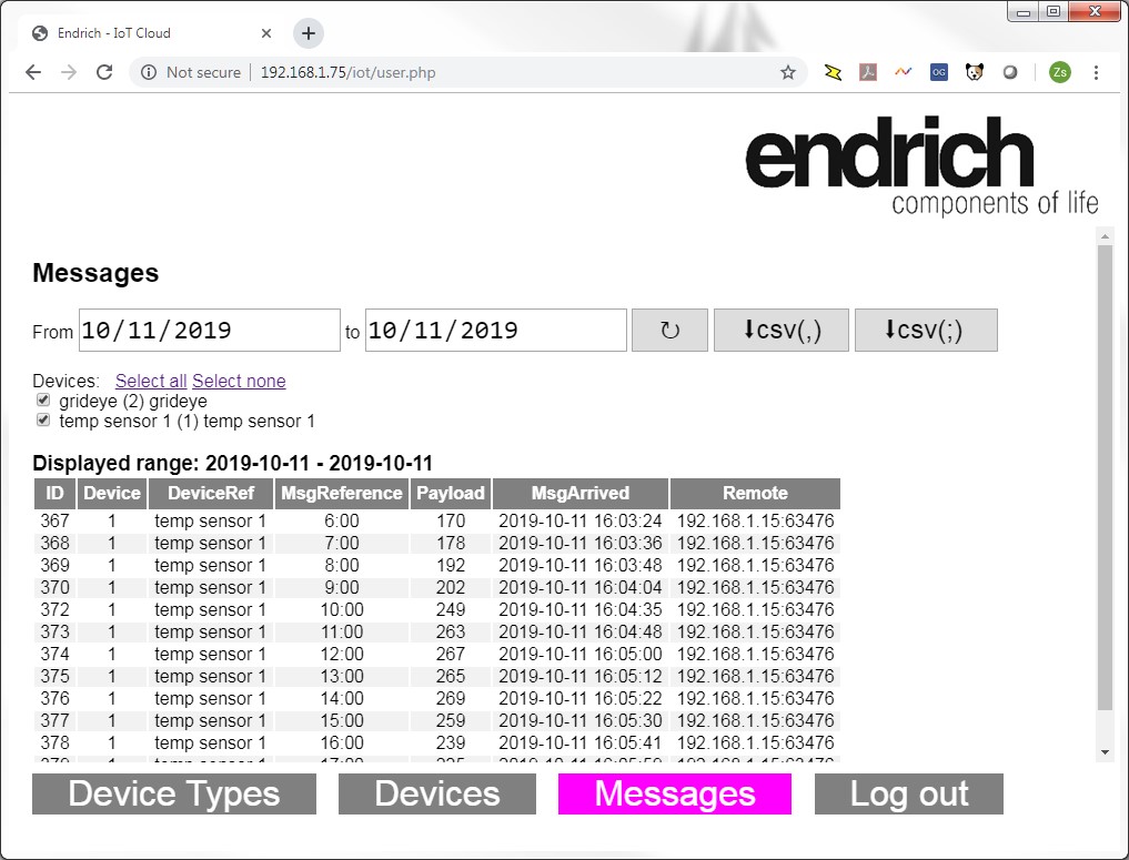
Click the Messages tab to search in the logs.
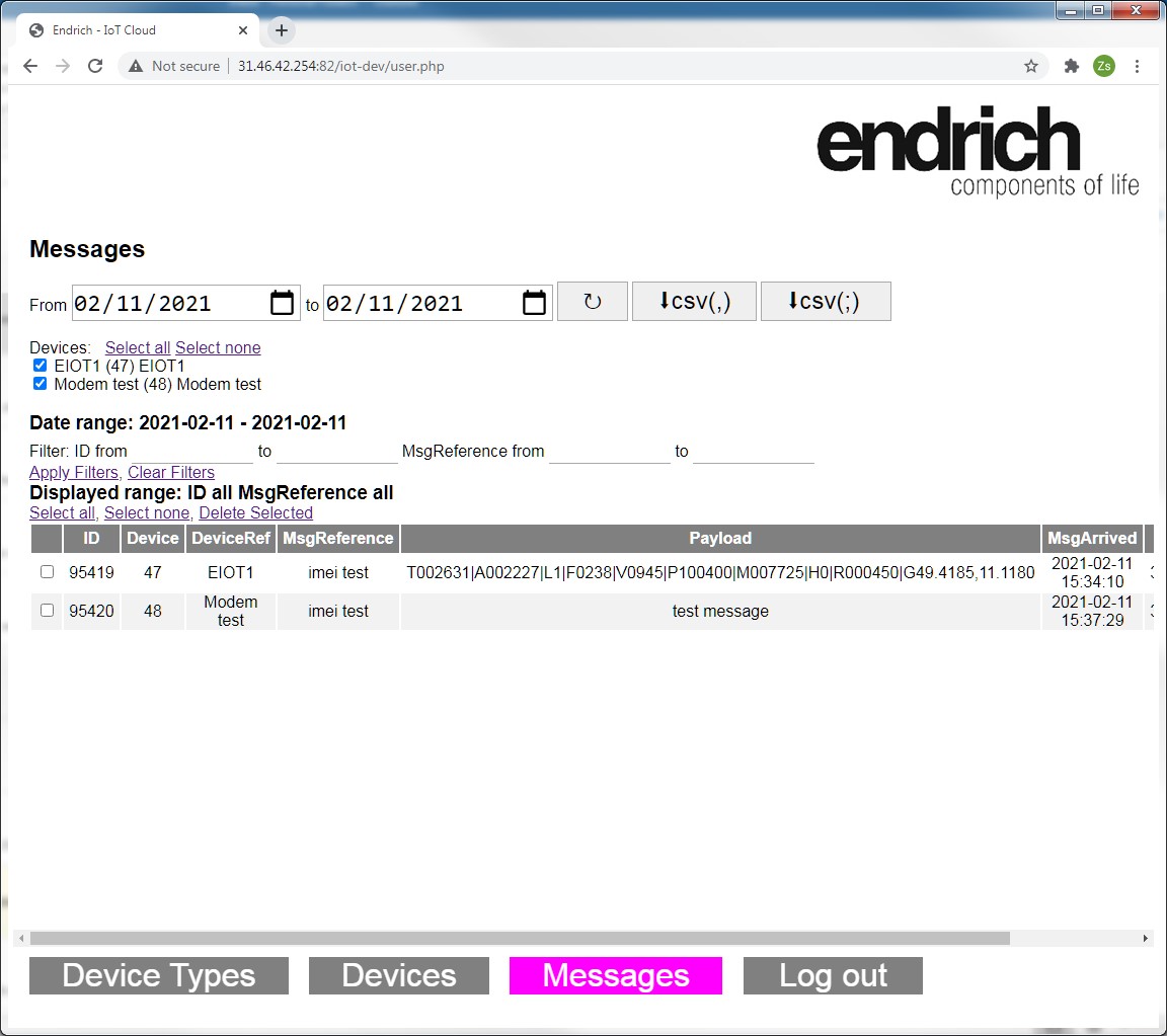
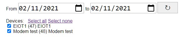
There is a search parameter definition area containing a date range, and selection of devices on the upper part of the screen. The date range is preset to the current date, and all users’ devices are selected by default. You can adjust the date range and change device selection, and retrieve the list again pressing the reload button (↻).
We have a message filtering block under this area:
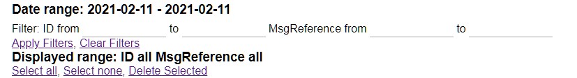
The function of this area is to provide a filter for the displayed content, and provide a bulk message deleting functionality for a certain range. The list can be sorted by clicking on the headings.

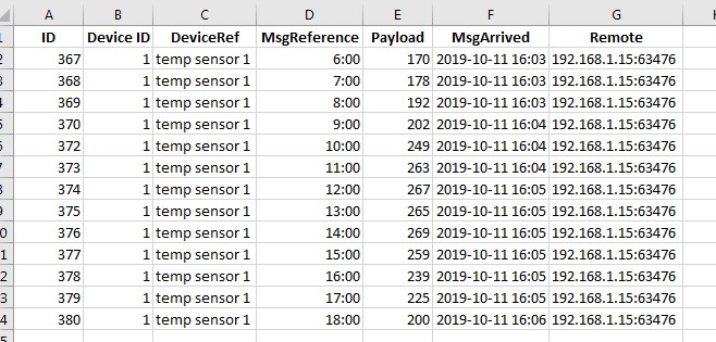
The content can be exported to CSV file with the two concerning buttons. Please make sure to use the one with the same list separator as your computer settings, usually semicolon (;) or comma (,). If the proper button has been clicked, the saved CSV file can be opened with Excel.
An easy example is to download the data of a single temperature sensor device into Excel or any other spreadsheet program:
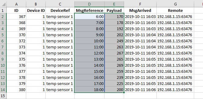
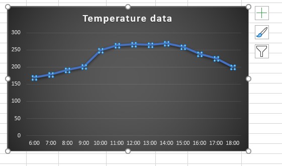
A few clicks and we have a graph about the visual representation of the measure temperature values over time. Just select the MsgReference and the Payload fields, and then insert a diagram :
Of course, the raw data can be also used as an input of a local processor program or could be converted to a local database. In case of having a special agreement, it is also possible to mirror the data to an external DB server, but that requires special setup. Please contact your sales representative in case of such requirement.
7.7 Summary of operation of Endrich Cloud Database
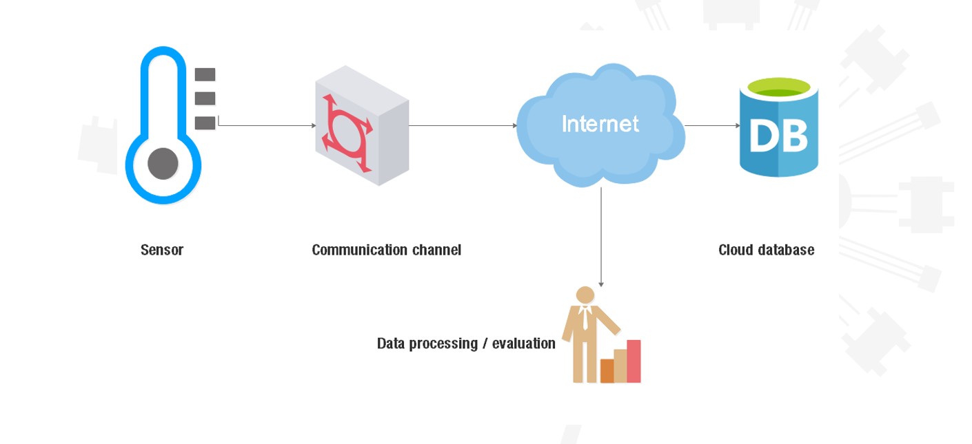
On the figure below we made a complete overview of the services offered by the Endrich Cloud DataBase system.
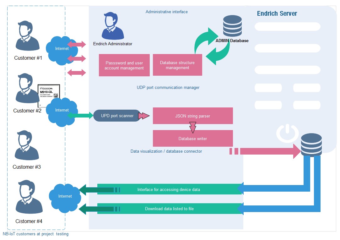
As described before all starts with application for a Databas Access, which will be granted to every user by the Endrich Administrator. Receiving the credentials You can access the Administrative Interface in prder to register the devices you would like to manage. Once they are created in the system all the data received from them would be possible to store in the Endrich CDB. Customer devices need to communicate via UDP port with the server and must use the JSON format described in 7.5. The 7/24 port scanner service expects the data in binary format (as explained) and after checking and providing basic security control it will parse it and write it into the database with the user and device identification, timestamp and remote address logged. Today there is no extensive data security carried out, we suggest customers need encryprion to send the payload encrypted, this service will store the data “as it is”, so encryption is kept. Later we will extend the service by introducing MQTT protocol. Sensor data can be sent as individual readings or the multi sensor approach is also supported.
Once the data is stored there are two ways of using them. Customer can either download the raw data through the Administration Interface limited to one or multiply devices for a certain time period. Or by using an external visuaization service provided by Endrich through a web server (http protocol). This later system is called the Endrich Visualization Gateway System and it can be accessed from any PCs, tablets or other mobile devices, offering a visual display of the sensor readings in Graph or in single data display format. The coming section of the software giude describes it in details.